
 Bally & Stern Dual Flipper EOS Switch Wiring
|
 
|
| |
|
|
|||||
|
- Game Parts & Supplies - Games for Sale - Ordering Info - Technical Articles - Game Service & Repair - Contact Us |
 Bally & Stern Dual Flipper EOS Switch Wiring Bally & Stern Dual Flipper EOS Switch Wiring
Many of the Technical Articles on our site contain information and directions involving electronics and circuit board repair. They are authored with the assumption that the reader has adequate experience and knowledge required to do the work being described. If you do not feel qualified, or are in any way uncomfortable doing any of the work described in any of the articles, then we strongly recommend enlisting the help of a qualified repair person or shop who can do the work for you. It may save you cost, time, and further repair work. We (Action Pinball & Amusement, LLC) are not responsible for any damage to you, your game, or your property, from doing any work on your game related to any of the articles listed on this site.
This article explains the correct wiring for flipper EOS (end-of-stroke) switch wiring for dual (upper & lower) flippers used on some early Bally and Stern solid-state pinballs 1977 through 1985. Bally games that used dual flippers on one side (or both sides) of the playfield, were Cybernaut, Eight Ball Champ, Eight Ball Deluxe, Flash Gordon, Future Spa, Harlem Globetrotters, Hotdoggin', Kings of Steel, Paragon, Space Invaders, Spy Hunter, Vector and more. Stern games that had dual flippers were Big Game, Cheetah, Lightning, Meteor, Seawitch and more. Some other makes/models may use similar designs, such as Williams Contact and Flash. Others did not, and instead used separate flipper coil wiring with two contacts on the flipper button switch in the cabinet, instead of using a 'dual' EOS switch on the lower flipper like Bally and Stern did. Some examples of this were Williams Black Knight, Black Knight 2000, Jungle Lord, Laser Cue, Pharaoh, Solar Fire and more. Proper wiring with notations for game wire colors are usually found in your game manual in the wiring/schematic diagram section. Manual wiring diagrams can be a bit vague, so please refer to our diagram below for a more visual layout of the correct wiring for dual (upper/lower) flippers. Bally & Stern Dual Flipper EOS Switch Wiring: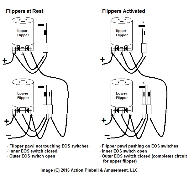 Items to note:
Diodes mounted between the solder lugs on the flipper coils have polarity ('+' and '-' ends) and wires must be connected to them in reference to how they are mounted on the coil, otherwise they can become shorted-out and you'll blow fuses every time you activate the flipper, and end up having to replace parts and do some repair work on the coil. Diodes have a silver band on one end, and no band on the other. The end with the band is the 'cathode' and is the positive (+) end. Power wire will always connect to the cathode end of the diode. The end without a band is the 'anode' and is the negative (-) end. Ground, or 'low side' of the circuit is always at the anode end. Diodes are depicted in the diagram above by the classic electronic symbol of a vertical line, and an 'arrow' coming out of it. The vertical line is the cathode (+) side (always to the left in the diagram below.) If you're not sure which wire going to your coil is the game's power (+) wire, refer to your game manual to determine wire color, or with power on, carefully measure between the suspect wire, and a ground point (metal chassis on cabinet) to see if you have positive voltage on that wire. If so, that's a good indication that you have identified the power wire (should show approx. 43vdc in Bally and Stern games). |
